Power factor correction (PFC) is not just a technical term, but a significant aspect that can greatly enhance the efficiency and reliability of electrical systems. Often underestimated, optimizing the power factor can lead to substantial cost savings, improved system performance, and a reduced environmental footprint.
This detailed guide aims to demystify power factor correction by exploring its underlying principles, practical applications, and methods. We’ll also provide step-by-step calculations to help you implement PFC in real-world scenarios.
What Is Power Factor and Why Does It Matter?
The power factor (PF) is a crucial metric in electrical systems. It is defined as the ratio of real power, measured in kilowatts (kW), to apparent power, measured in kilovolt-amperes (kVA).
PF=Apparent Power (kVA)Real Power (kW)
Understanding the Components:
-
Real Power (P): This is the power consumed by electrical devices to perform practical work, such as lighting, heating, or running motors. It is measured in watts (W) and often kilowatts (kW).
-
Reactive Power (Q): Reactive power is required to maintain magnetic fields in inductive loads like motors, transformers, and inductors. It is measured in volt-amperes reactive (VAR).
-
Apparent Power (S): Apparent power combines real and reactive power, and its unit is volt-amperes (VA).
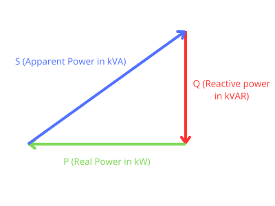
The relationship between these three powers can be represented as a right triangle, where:

- Apparent power is the hypotenuse.
- Real power is the adjacent side.
- Reactive power is the opposite side.
The power factor is the cosine of the angle between real and apparent power.
The Ideal Power Factor
An ideal power factor is 1 (or unity), which occurs when the load is purely resistive, meaning no reactive power is involved. In practical systems, however, inductive loads like motors, HVAC, and transformers introduce reactive power, reducing the power factor.
Problems Caused by Poor Power Factor
Low power factor can lead to several inefficiencies in electrical systems, including:
-
Increased Energy Costs:
Utility companies charge for apparent power, so a low power factor means higher demand charges. This can significantly increase operational costs.
-
Reduced System Capacity:
A low power factor increases the current flow in electrical systems, reducing the available capacity for other equipment.
-
Voltage Drops:
Higher currents caused by a poor power factor can lead to voltage drops, negatively impacting the performance of sensitive equipment.
-
Penalties from Utilities:
Many utility companies impose penalties for power factors below a certain threshold (typically 0.9). Correcting the power factor helps avoid these fines.
-
Heat Losses:
Higher current due to a low power factor generates additional heat in conductors and equipment, potentially leading to premature failure.
Benefits of Power Factor Correction
Investing in power factor correction offers a wide range of benefits:
- Reduced Demand Charges: Lower apparent power leads to lower utility demand charges.
- Improved Efficiency: Reducing reactive power minimizes energy losses in conductors and equipment.
- Increased System Capacity: Correcting power factor frees up capacity in the existing system, allowing additional loads to be connected.
- Enhanced Voltage Regulation: Power factor correction improves voltage stability, which is critical for sensitive equipment.
- Environmental Benefits: power factor correction reduces the overall carbon footprint by optimizing energy usage.
Methods of Power Factor Correction
There are several techniques to improve power factor, each suited to different types of systems:
1. Capacitor Banks
Capacitor banks are the most common method of power factor correction. Capacitors produce leading reactive power that cancels out the lagging reactive power generated by inductive loads.
Example Calculation:
Suppose a system operates at a power factor of 0.7 and consumes 100 kW of real power. To improve the power factor to 0.95, the required reactive power (QC) from the capacitor is:
QC=P×(tancos−1(0.7)−tancos−1(0.95))
Using P=100kW:
QC=100×(1.428−0.329)≈109.9kVAR
A capacitor bank rated at 109.9 kVAR would be needed to achieve the desired power factor.
2. Synchronous Condensers
Synchronous condensers are synchronous motors operating without mechanical load. They generate reactive power, improving the power factor. This method is ideal for large industrial systems but requires higher maintenance than capacitor banks.
3. Phase Advancers
Phase advancers are devices connected to the rotor circuit of induction motors. They improve the power factor by reducing the reactive power drawn from the supply. This technique is used primarily in industries with high motor loads.
4. Variable Frequency Drives (VFDs)
VFDs improve motor efficiency by controlling speed and help maintain a higher power factor. They are particularly useful in applications where motor loads vary frequently.
Power factor correction is a versatile tool used across multiple sectors to enhance efficiency and reliability.
Power factor correction is essential across various sectors:
1. Industrial Applications
Factories often operate heavy machinery with significant inductive loads. Power factor correction reduces energy costs and improves voltage stability, ensuring reliable operation.
2. Commercial Buildings
HVAC systems, lighting, and elevators in commercial setups contribute to a low power factor. Installing capacitor banks improves energy efficiency and lowers utility bills.
3. Renewable Energy Systems
In renewable energy systems, power factor correction ensures smooth integration of wind and solar power into the grid. It helps maintain grid stability and prevents voltage fluctuations.
4. Utility Networks
Utility companies use power factor correction to reduce transmission losses and improve power delivery efficiency.
Step-by-Step Example: Power Factor Correction
Scenario:
A manufacturing plant consumes 300 kW of real power with a power factor of 0.6. The goal is to improve the power factor to 0.95. Calculate the required capacitor size.
Step 1: Calculate the Initial Reactive Power (QInitial)
QInitial=P×tancos−1(0.6)
QInitial=300×tan(53.13∘)≈400kVAR
Step 2: Calculate the Desired Reactive Power (QDesired)
QDesired=P×tancos−1(0.95)
QDesired=300×tan(18.19∘)≈98.1kVAR
Step 3: Determine the Capacitor Size (QC)
QC=QInitial−QDesired
QC=400−98.1=301.9kVAR
The plant requires a capacitor bank at approximately 302 kVAR to achieve the desired power factor.
Conclusion
Power factor correction is a cornerstone of efficient and sustainable electrical systems. By implementing the right methods—whether capacitor banks, synchronous condensers, or advanced techniques like VFDs —businesses can achieve significant cost savings, enhanced system performance, and reduced environmental impact.
Start optimizing your power factor today to get the full potential of your electrical systems and contribute to a greener future.
Credits
Photo by Thomas Kelley on Unsplash


