
Current Transformer Complete Guide: How CT Sensors Work, SCT-013 Wiring & Sizing
- Admin: IDAR Mohamed
- 08 Jun 2026
- 0
Clip an SCT-013 around a live cable, connect the 3.5mm jack, and a microcontroller can read line current without touching a high-voltage terminal. That simplicity is real — but the interface circuit behind it needs to be correct, or the readings will drift, clip, or be meaningless. This guide covers how CTs work, which SCT-013 variant to pick, how to calculate the burden resistor, and when to step up to industrial-grade sensors.
Table of Contents
- How a Current Transformer Works
- Types of Current Transformers
- Understanding the SCT-013 Series
- Burden Resistor Calculation
- Wiring an SCT-013 to Arduino or ESP32
- CT Meter Applications in Industry
- Choosing a Current Transformer Manufacturer
How a Current Transformer Works
A current transformer (CT) operates on the same principle as any transformer, but with a critical distinction: instead of stepping voltage up or down, it steps down current while isolating the measuring circuit from the high-voltage conductor being monitored.
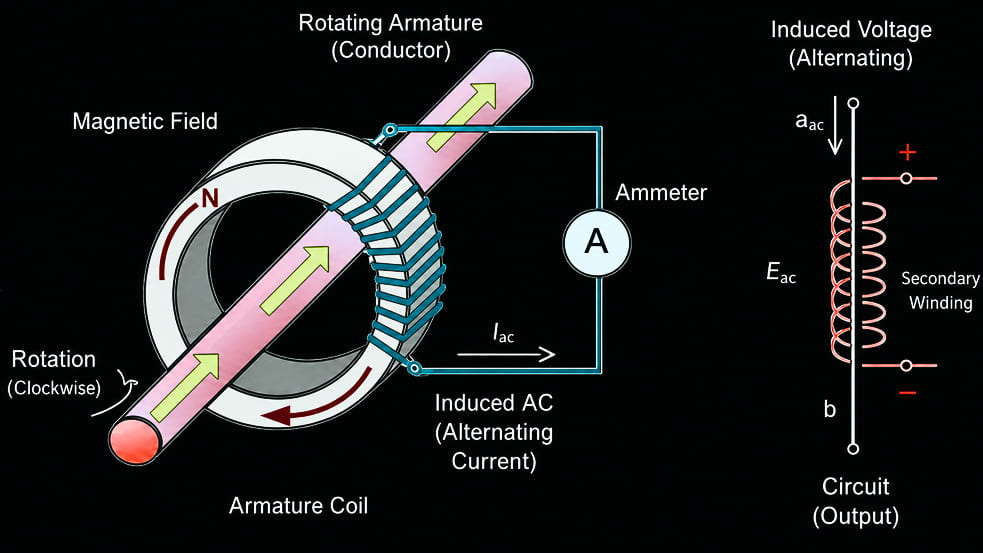
The primary "winding" is typically just the conductor passing through the CT's core — a single pass counts as one turn. The secondary winding, wound many times around the toroidal core, produces a proportional but much smaller current. A 100A:5A CT produces 5A for every 100A flowing in the primary.
The key equation:
Where:
- I₁ = Primary (line) current
- I₂ = Secondary output current
- N₁ = Primary turns (usually 1)
- N₂ = Secondary turns
For a 100A:50mA CT like the SCT-013-000 (with N₁ = 1):
The SCT-013-000 is rated at 100A:50mA, meaning that when 100 A flows through the primary conductor, the CT outputs 50 mA on its secondary winding, corresponding to a current ratio of 2000:1.
Important safety rule: Never open-circuit a CT secondary while current flows in the primary. Without a load, the magnetic flux has nowhere to go and will develop a dangerously high voltage across the open terminals.
Types of Current Transformers
The choice between core types comes down mainly to installation constraints — specifically, whether you can thread the conductor through during installation or need to clamp around it afterwards.
Wound-Core (Solid Core) CTs
Wound-core current transformer showing a conductor passing through a solid magnetic core for precise current measurement.
The wire must be threaded through the opening during installation. More accurate than split-core equivalents at the same price point. Used in metering panels and revenue-grade applications where accuracy class (0.2S, 0.5S) matters.
Split-Core CTs
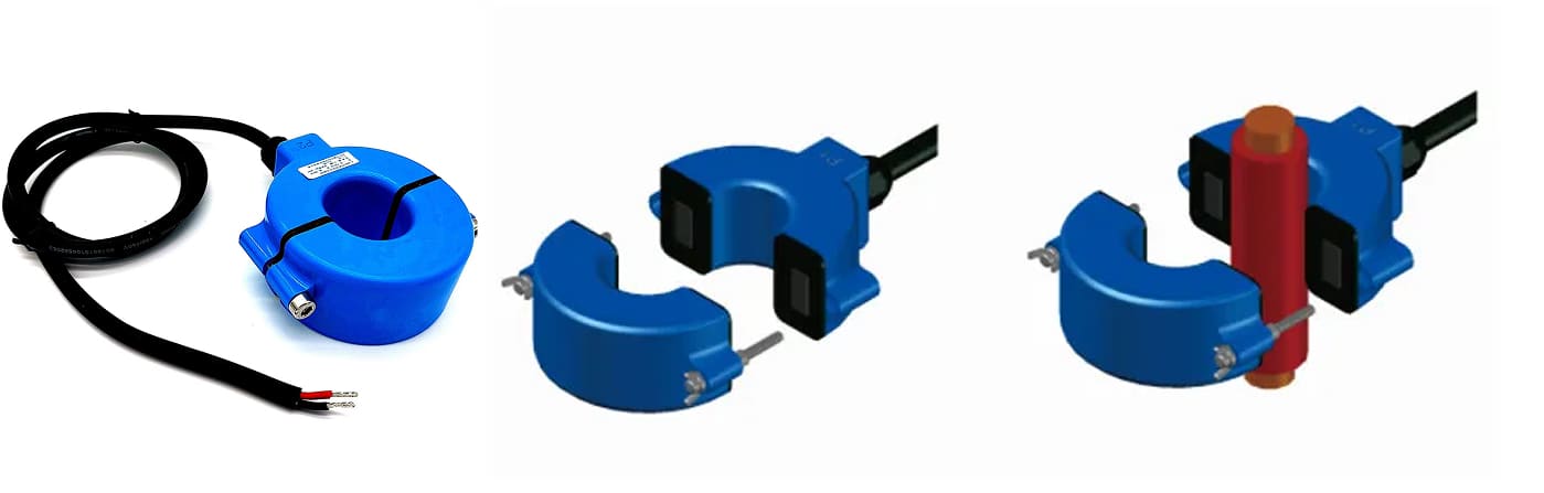
Split-core current transformer installed around an existing conductor without disconnecting the circuit.
The core hinges or separates to clamp around an existing conductor without breaking the circuit. This makes retrofitting into live panels straightforward. Accuracy is slightly lower than equivalent solid-core CTs, but for most monitoring applications (±1–3%) this is acceptable.
Bar/Busbar CTs
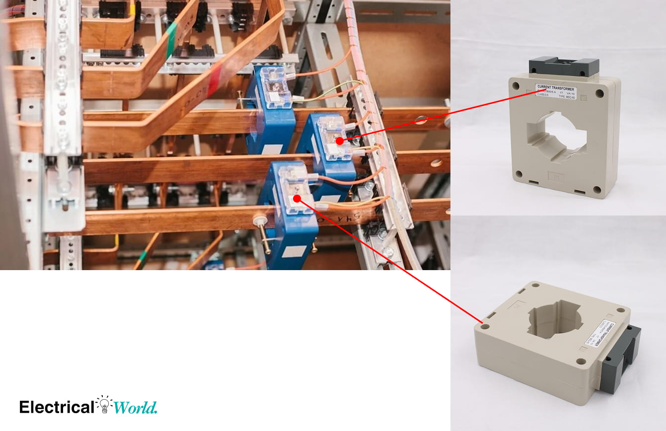
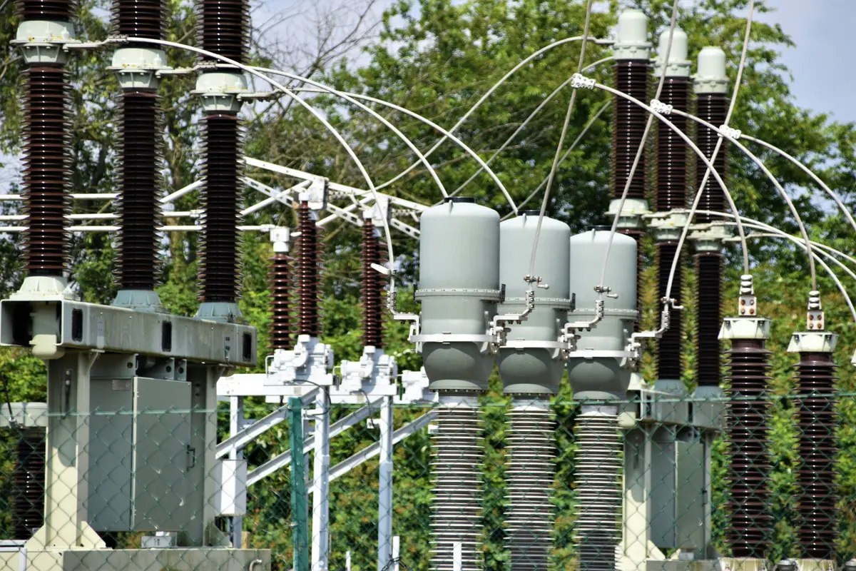
Busbar current transformer used in switchgear and power distribution systems to monitor high-current busbars.
Designed for busbars rather than insulated cables — the busbar itself acts as the primary conductor. Common in switchgear and distribution panels.
Rogowski Coils
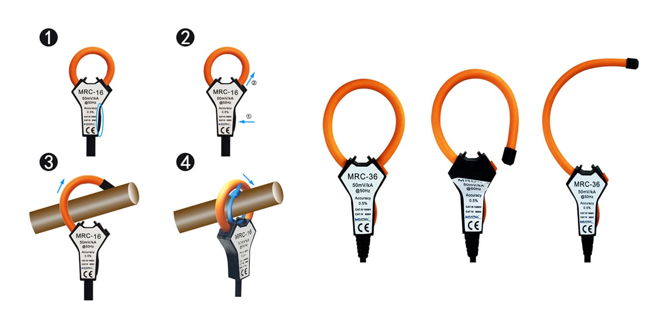
Rogowski coil current sensor measuring high AC currents with a flexible air-core coil and integrator circuit.
A flexible, open-ended coil that wraps around a conductor with no core saturation and a wide dynamic range. It needs an integrating circuit to produce usable output. Used for very high-current applications or where a standard core would saturate.
Understanding the SCT-013 Series
The SCT-013 is a split-core CT manufactured by YHDC. The 3.5mm jack output makes it easy to interface with microcontroller ADCs, and a few variants cover the most common monitoring ranges:
| Model | Primary Range | Secondary Output | Internal Burden |
|---|---|---|---|
| SCT-013-000 | 0–100A | 0–50mA | None (external required) |
| SCT-013-005 | 0–100A | 0–5V | Internal |
| SCT-013-030 | 0–30A | 0–1V | 62Ω internal |
| SCT-013-060 | 0–60A | 0–1V | Internal |
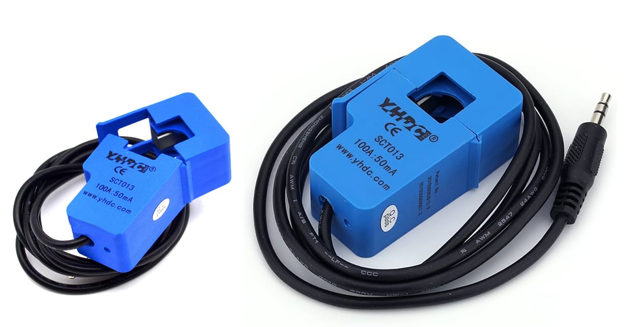
The SCT-013-000 is the raw current output variant — it produces 0–50mA proportional to 0–100A on the primary. To use it with a microcontroller ADC, you need an external burden resistor and a voltage bias circuit. More on that below.
The -030 is limited to 30A but includes an internal burden resistor, outputting 0–1V directly. For household circuit monitoring where most loads stay under 25A, it's the simpler starting point.
Burden Resistor Calculation
For the SCT-013-000, the burden resistor converts secondary current to a voltage the ADC can read.
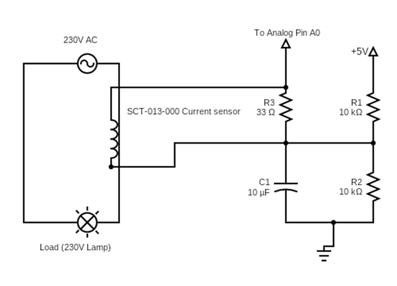
Why the bias circuit matters: AC current is bidirectional — the waveform swings positive and negative. An ADC can't read negative voltages. The solution is to bias the CT output to VCC/2, so the waveform rides above GND throughout the full cycle.
Burden resistor formula:
For a 3.3V system (ADC peak = 1.65V) and SCT-013-000 (max 50mA):
Power dissipation:
A standard 0.25W resistor handles this comfortably. Use 1% tolerance for better accuracy.
Voltage bias circuit: Two equal resistors (10kΩ each) in series from VCC to GND. The midpoint connects to the CT− terminal. This pulls the output signal to VCC/2 so the ADC sees values between 0 and VCC rather than swinging negative.
Wiring an SCT-013 to Arduino or ESP32
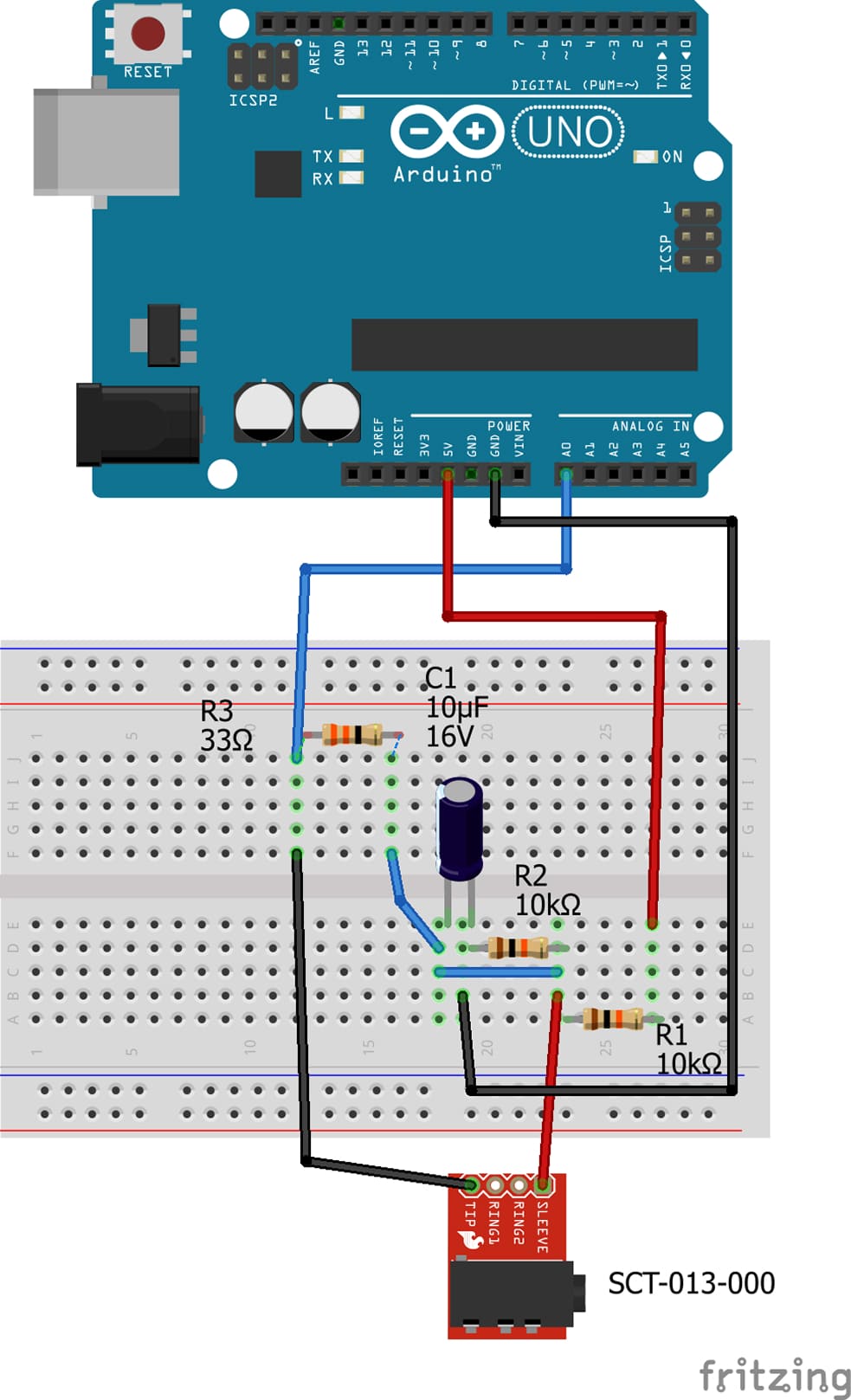
Figure: SCT-013-000 wired to an Arduino analog input with 33Ω burden resistor and 10kΩ bias divider.
Components needed:
- SCT-013-000 (or -030 for simpler wiring)
- 33Ω burden resistor (omit for -030)
- Two 10kΩ resistors (bias divider)
- 10µF capacitor (across bias midpoint to GND)
- 3.5mm audio jack socket
Wiring steps:
- Connect the 3.5mm jack: tip = CT+, sleeve = CT−
- Place the 33Ω burden resistor between CT+ and CT−
- Build the bias divider: two 10kΩ resistors from VCC to GND; midpoint goes to CT−
- Connect CT+ to the analog input pin
- Add a 10µF capacitor from the bias midpoint to GND
Use the EmonLib library by OpenEnergyMonitor. emon1.calcIrms(1480) gives RMS
current directly; emon1.calcVI(20, 2000) reads both current and voltage. Calibrate
against a known resistive load — a 1400W heater on a 230V supply draws ~6,08A and
makes a clean reference point.
#include "EmonLib.h"

EnergyMonitor emon1;

void setup() {
  Serial.begin(9600);

  // CT on A0
  emon1.current(A0, 60.6);  // calibration depends on your CT
}

void loop() {
  double Irms = emon1.calcIrms(1480);

  Serial.print("Current RMS: ");
  Serial.print(Irms);
  Serial.println(" A");

  delay(1000);
}
CT Meter Applications in Industry
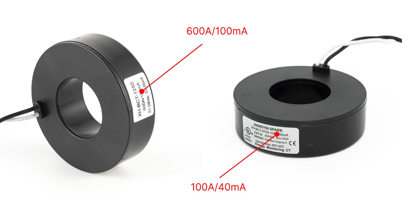
Industrial CT metering works on the same principle as the SCT-013, but with tighter accuracy requirements and standardized secondary outputs.
Energy metering (CT meter): Utility revenue meters and sub-meters use CT inputs to avoid routing high-amperage conductors through the meter itself. A standard CT meter accepts 5A secondary input (from a 100A:5A or 400A:5A CT) and multiplies by the ratio internally. The meter and CT are always specified together — the CT's burden VA rating must exceed the meter's burden requirement.
Motor protection relays: Overload relays sample CT secondary current to detect locked-rotor, phase-loss, or overload. Thermal inverse curves typically respond in 1–10 seconds depending on how far above the trip threshold the current sits.
Differential protection: Power transformers and generators use matched CT sets on primary and secondary windings. Under normal operation, the secondary currents cancel. A fault inside the protected zone creates an imbalance that trips the differential relay within 1–2 cycles — 20–40ms on a 50Hz system.
Power quality analyzers: Clamp-on CTs (a portable split-core variant) connect to handheld or panel-mounted analyzers to measure harmonics, power factor, and demand profile without disconnecting any wiring.
Choosing a Current Transformer Manufacturer
Manufacturer selection follows accuracy class. Mixing up the tiers is the most common mistake — paying for IEC 0.2S accuracy in an IoT sensor application, or expecting ±1% from a $4 YHDC unit in a billing system.
YHDC makes the SCT-013 series and a broader range of split-core and solid-core CTs. At ±3% accuracy, they're adequate for energy monitoring dashboards, demand profiling, and IoT projects. They're available from Mouser, AliExpress, and Amazon.
For building energy management systems where sub-metering feeds tenant billing, the accuracy bar rises to Class 1 (±1%). Talema, Coilcraft, and Murata cover this tier with better thermal stability than budget CTs. Worth the price difference when someone is paying based on the readings.
Revenue-grade and protection-grade applications — utility metering points, relay coordination, switchgear — require IEC 61869-2 compliance with accuracy classes of 0.2S or 0.5S. ABB, Schneider Electric, and Siemens are the standard choices here. These units are type-tested and come with calibration certificates.
Key specifications to check regardless of manufacturer:
- Accuracy class (0.1, 0.2S, 0.5S, 1, 3)
- Burden VA rating (must exceed your meter's burden)
- Insulation voltage (match to the circuit voltage)
- Frequency range (50Hz vs. 60Hz)
- CT ratio and rated primary current
A Note on Getting This Right
The SCT-013-000 with a 33Ω burden and 10kΩ bias divider is the most flexible starting point for monitoring projects — EmonLib handles the RMS math, and the circuit is straightforward to build. Moving up to industrial accuracy means specifying burden VA and accuracy class alongside the CT ratio. Get those two right and the rest follows.
Don't open-circuit the secondary. That's the one error that can turn a sensing device into a hazard.
🔗 Related Posts
- Understanding Induction Motors: Working Principle, Calculations, and Applications
- PID Controller Explained: How It Works, Tuning Methods & Real-World Applications
- Transformer Sizing: Complete Guide with Calculations, Charts & Selection Criteria
- Contactor vs Relay: Complete Guide with Applications & Selection Criteria
- Modbus Protocol: Complete Guide to RTU, TCP & ASCII with Wiring Examples
Helpful Calculators
- Voltage Drop Calculator
- Ohm's Law Calculator
- Power Factor Calculator
- AC DC Current Calculator
- Capacitor and Inductor Reactance Calculator
- Resistor Color Code Calculator
- Transformer Ratio Calculator
- Series Parallel Resistance Calculator
Credits
- Photo by Waldemar Brandt on Unsplash
⭐ Was this article helpful?
IDAR Mohamed
Electrical Engineer
Electrical Engineer specialized in power systems, electrical installations, and energy efficiency. Passionate about simplifying complex electrical concepts into practical guides. (University of applied sciences graduate, with experience in HV/LV systems and industrial installations.)
- Sensors and Measurement
- Electrical Testing and Calibration
- Industrial IoT