

Servo Motor vs Stepper Motor: Which One Actually Belongs in Your Build?
- Admin: IDAR Mohamed
- 08 Jun 2026
- 0
Two systems, a stepper motor vs. a servo motor, same spec sheet: same speed rating, same torque class, same motion profile. One confirms it reached the commanded position. The other assumes it did. That assumption is where it breaks down. A stepper motor moves in fixed incremental steps and treats every pulse as a completed move. A servo motor uses an encoder to verify actual shaft position on each control cycle and corrects any error before the next command runs. Whether that feedback loop exists determines how each system behaves under load, at speed, and when conditions shift without warning.
Table of contents
- How each motor works
- Open-loop vs closed-loop: what it means in practice
- Positioning resolution and the cost of missed steps
- Torque-speed derating
- Wiring and commissioning complexity
- Cost comparison across multiple axes
- Decision guide: which motor fits which application
- Full comparison table
- FAQs
How each motor works
Stepper motors
A stepper motor divides a full rotation into fixed equal steps. The standard is 200 steps per revolution (1.8° per step). Each electrical pulse from the driver advances the rotor exactly one step. No encoder. No position verification.
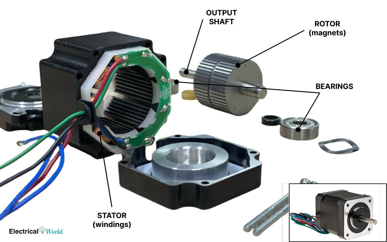
The rotor is a permanent magnet. The stator contains a ring of energized poles (teeth). Switching current through those poles in sequence pulls the rotor from one detent position to the next. Holding position requires keeping the windings energized, which is why steppers run warm even when stationary.
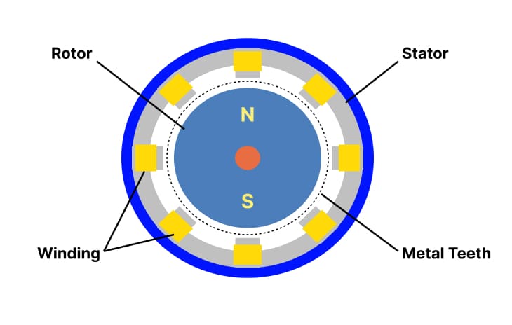
Figure: The stepper rotor advances one fixed step per electrical pulse. No feedback path exists in a standard open-loop configuration.
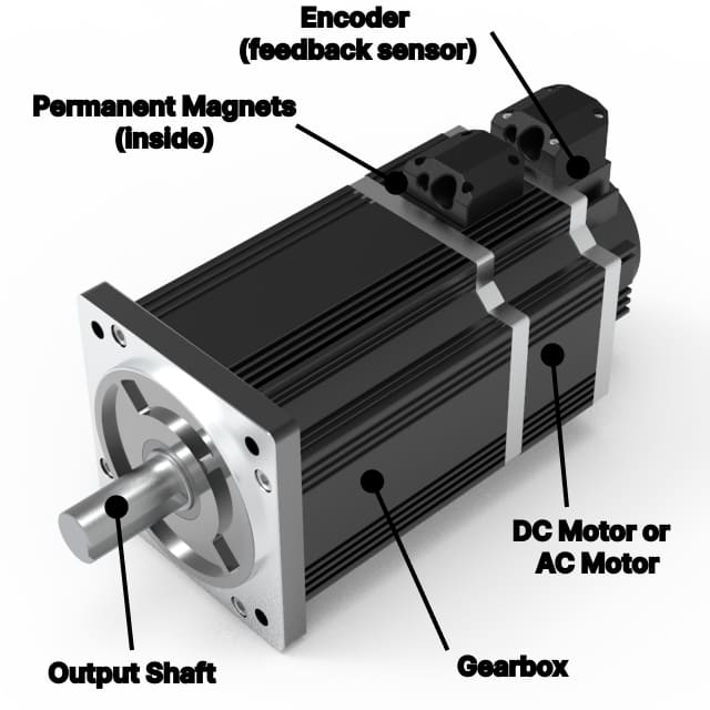
Servo motors
A servo motor is a brushless AC or BLDC motor paired with an encoder. The encoder reports actual shaft position back to the drive continuously. The drive compares commanded position against actual position and adjusts current output to correct any error. That correction loop runs in real time, typically at 1 kHz or faster on modern drives.
Encoder resolution ranges from 2,500 PPR on entry-level systems to 17-bit (131,072 counts/rev) on precision servo drives.
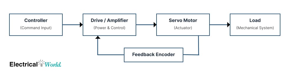
Figure: The servo drive continuously compares commanded and actual shaft position, correcting any error within each control cycle.
Open-loop vs closed-loop: what it means in practice
A stepper system is open-loop. The controller sends pulses and assumes they executed. This assumption holds when the load is predictable and well within the motor's torque rating at the operating speed. When it doesn't hold, the motor slips steps without signaling a fault.
A servo system is closed-loop. The drive knows where the shaft is at all times. If the position error grows beyond a set threshold, the drive faults and stops. The machine halts with a clear alarm rather than continuing to produce bad output.
On a production line, that distinction changes how faults are managed. Open-loop systems can produce defective parts for an entire shift before anyone notices a positional offset. Closed-loop systems alarm on the first fault.
Some closed-loop stepper drives are available, using an encoder to detect stall and fault out. They are a reasonable middle ground for applications that need basic fault detection at lower cost than a full servo system. Performance under dynamic load is still below a true servo, but fault visibility improves significantly.
Positioning resolution and the cost of missed steps
Stepper linear resolution
For a stepper driving a lead screw, linear resolution is:
Example: NEMA 23, 200 steps/rev, 1/16 microstepping, 5 mm/rev lead screw
This is the theoretical control resolution. Actual mechanical accuracy is further limited by lead screw pitch error, backlash, and mechanical compliance. But the motion controller resolution is the upper ceiling.
What one missed step actually costs
Position error from missed steps:
Running the same motor at full step (no microstepping), losing 8 steps under a load spike:
The controller keeps counting from its last known position. On the next move, it starts 0.2 mm off. On a part with a ±0.05 mm tolerance, that's a guaranteed reject. The machine won't indicate anything went wrong.
Servo encoder resolution for comparison
With a 2,500 PPR encoder (10,000 counts/rev in quadrature) and the same 5 mm lead screw:
A 17-bit encoder (131,072 counts/rev):
Beyond the resolution advantage, the servo corrects position errors within the control loop. A 3-count deviation from commanded position due to load gets corrected on the next cycle. There is no silent accumulation.
| Motor type | Encoder / step config | Resolution on 5 mm pitch screw |
|---|---|---|
| Stepper (full step) | 200 steps/rev | 25 μm per step |
| Stepper (1/16 micro) | 3,200 steps/rev | 1.56 μm per step |
| Servo (2,500 PPR) | 10,000 counts/rev | 0.5 μm per count |
| Servo (17-bit) | 131,072 counts/rev | ~0.038 μm per count |
Torque-speed derating
Why stepper torque drops with speed
As rotor speed increases, winding inductance limits how quickly current can build up between steps. Less current means less electromagnetic force, which means less torque. The effect is significant above 300 to 400 rpm on most NEMA 23 motors.
Approximate torque output at different speeds for a typical NEMA 23 motor (rated holding torque: 2.8 N·m):
| Speed (rpm) | Available torque | % of holding torque |
|---|---|---|
| 0 (holding) | 2.80 N·m | 100% |
| 200 rpm | 1.80 N·m | 64% |
| 400 rpm | 1.10 N·m | 39% |
| 600 rpm | 0.60 N·m | 21% |
| 800 rpm | 0.30 N·m | 11% |
These values are representative of a typical driver at 48 VDC. Always verify against the manufacturer's torque-speed curve for the specific motor and driver combination in use.
The consequence: a stepper sized to move a 2.5 N·m load at low speed may have nothing left at 600 rpm. A motor that looks safe on the data sheet at rated holding torque can be completely undersized at the actual operating speed.
Servo torque curve
A servo motor paired with its drive delivers relatively flat torque across its entire rated speed range. A 400 W servo with a 1.27 N·m continuous torque rating will hold that torque from 0 to 3,000 rpm before dropping off. At 600 rpm, the servo in this comparison delivers more than twice the torque of the stepper above.
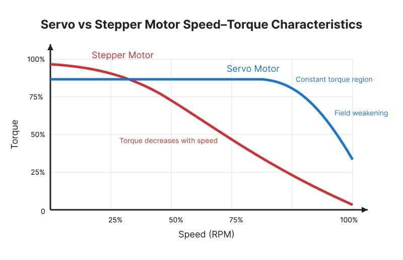
Figure: Stepper torque falls sharply with speed. Servo torque remains flat up to rated speed, then drops. For high-speed or variable-load applications, the servo has a fundamental advantage.
Wiring and commissioning complexity
The stepper system is simpler to set up. The wiring path is: power supply, driver, pulse/direction signals from the controller (PLC output, Arduino, or motion controller), motor cable. Current adjustment is done with a potentiometer on the driver. Most stepper drivers need no software configuration.
A servo system requires: a servo drive, shielded and grounded encoder feedback cable, and PID gain tuning. The PID Controller tuning guide covers the gain tuning process in detail, but expect to spend real time on it for high-speed or high-inertia loads. Poorly tuned servos oscillate, overshoot, and sometimes fault continuously until the gains are adjusted.
For applications maintained by technicians without drive training, a stepper setup is easier to troubleshoot. For high-performance applications, the commissioning overhead of the servo is a one-time cost that pays back in reliability.
Cost comparison across multiple axes
Per-axis component costs
The following breakdown reflects typical real-world CNC / motion control pricing ranges, not best-case hobby pricing.
| Component | Stepper System (per axis) | Servo System (per axis) |
|---|---|---|
| Motor | 60 | 400+ |
| Driver / Drive | 40 | 300+ |
| Feedback system (encoder / cable) | Not required | 40 (usually included in servo kits) |
| Total per axis | 120 | 600+ |
4-axis machine calculation
Stepper option:
Typical breakdown:
- Motors: 4 × $40 = $160
- Drivers: 4 × $25 = $100
Estimated total:
$120 – $500 (realistic range)
Servo option:
Typical breakdown:
- Motors: 4 × $200 = $800
- Drivers: 4 × $150 = $600
Estimated total:
$1200 – $3000 (depending on servo class)
The servo option costs 3× to 8× more per axis than a stepper-based system. that's ~$1,000 to $2,500+ additional cost per machine in component cost alone, before factoring in commissioning time.
Whether that gap is justified depends entirely on the application. For a 3D printer or label indexer, it usually isn't. For a robotic welding fixture, pharmaceutical dispensing machine, or any system where a missed step means a scrapped part or a safety incident, the servo's fault detection and torque consistency justify the premium.
Decision guide: which motor fits which application
Use a stepper when:
- Speed stays below 500 rpm at operating load
- Load is predictable and stays within 50% of rated holding torque at the operating speed
- The machine has physical home switches or limit stops (errors reset on homing)
- Budget is a hard constraint
- Applications: 3D printers, label indexers, valve actuators, dispensing equipment, lab automation
Use a servo when:
- Speed is high or variable across the duty cycle
- Load changes unpredictably mid-move (cutting loads, pick-and-place inertia variation)
- Confirmed positioning and real-time fault detection are required
- Downtime or defective output carries significant cost
- Applications: CNC machining, packaging lines, pick-and-place, robotics, medical devices
Neither motor type is universally better. The right choice comes from matching the motor's control architecture to the actual load profile and fault tolerance of the application. In many installations, servos are specified where a closed-loop stepper or even a standard stepper would perform identically at a fraction of the cost. The reverse failure is less common, but more expensive when it happens.
For wiring and protection once the motor is selected, the Motor Overload Protection Sizing Guide covers relay and overload selection. For cable sizing to the motor terminal box, see the Motor Cable Sizing Guide for 5 HP and 10 HP motors.
Full comparison table
| Feature | Stepper motor | Servo motor |
|---|---|---|
| Control type | Open-loop (standard) | Closed-loop |
| Position feedback | Not required | Encoder required |
| Torque at low speed | High | Moderate to high |
| Torque at high speed | Drops sharply (see table) | Relatively flat to rated speed |
| Step loss detection | None | Faults immediately |
| Typical resolution (5 mm screw) | 1.56 μm at 1/16 step | 0.5 μm at 2,500 PPR |
| Wiring complexity | Low | Higher (shielded cable, PID tuning) |
| Best fit | Low speed, predictable load | High speed, variable load, precision |
FAQs
Can a stepper replace a servo in a production machine? In some cases, yes. If speed is low, the load is predictable, and fault detection is not a requirement, a stepper is a cost-effective option. For high-speed or precision applications where a missed step produces a reject or causes mechanical damage, it is not a reliable substitute.
Why does a stepper vibrate more than a servo? The discrete step movement creates mechanical resonance, most pronounced in the 100 to 200 rpm range. Microstepping smooths the motion but does not eliminate resonance. Servo drives produce inherently smoother motion because the current output adjusts continuously rather than switching between fixed detent positions.
What happens if the load exceeds the stepper's torque at speed? The rotor slips past a step. The driver does not detect this. The controller keeps counting from its last assumed position. Position errors accumulate silently until the axis hits a limit switch, produces a defective part, or a homing cycle resets the position reference.
For variable-speed AC motor control, the VFD Complete Guide covers drive selection, parameter setup, and energy savings calculations. If the application uses PWM to control DC motor speed rather than a stepper or servo, the PWM Motor Control guide is the relevant reference. For starting and protection of larger induction motors, see the Soft Starter guide and the Star-Delta Starter wiring guide.
🔗 Related posts
- Variable Frequency Drive (VFD): The Complete Guide to Working Principles, Types, and Applications
- Motor Overload Protection: Complete Sizing Guide with Charts and Selection Criteria
- Motor Cable Size for 5 HP and 10 HP: Complete Selection Guide with Charts
- PID Controller Explained: How It Works, Tuning Methods and Real-World Applications
- PWM Motor Control: Complete Guide to DC Motor Speed Control with Pulse Width Modulation
- Soft Starter Working Guide: How It Works, Sizing, Wiring & When to Use It
Helpful calculators
- Voltage Drop Calculator
- Ohm's Law Calculator
- Power Factor Calculator
- AC DC Current Calculator
- Capacitor and Inductor Reactance Calculator
- Resistor Color Code Calculator
- Transformer Ratio Calculator
- Series Parallel Resistance Calculator
Credits
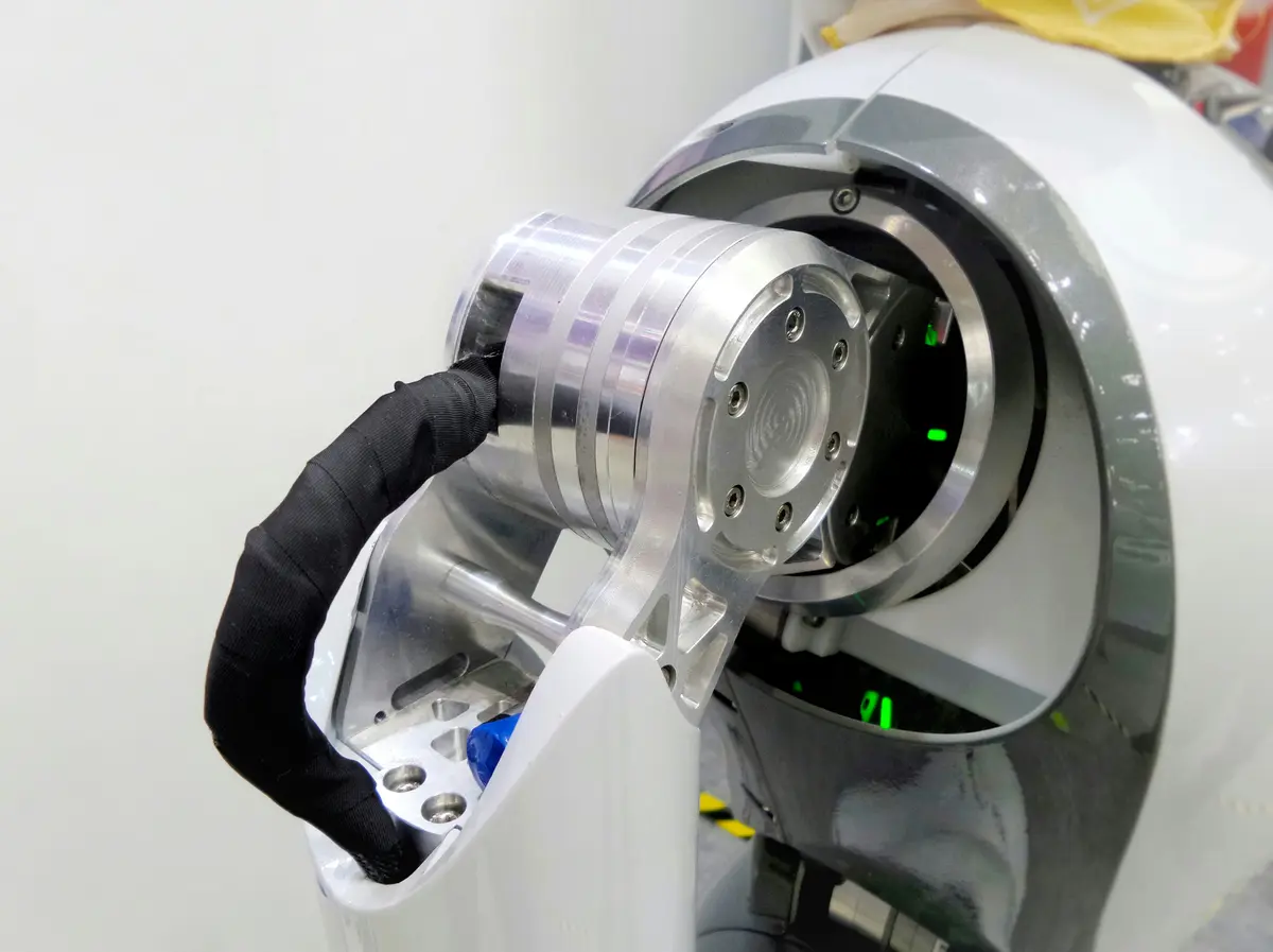
- Photo by Possessed Photography on Unsplash
⭐ Was this article helpful?
IDAR Mohamed
Electrical Engineer
Electrical Engineer specialized in power systems, electrical installations, and energy efficiency. Passionate about simplifying complex electrical concepts into practical guides. (University of applied sciences graduate, with experience in HV/LV systems and industrial installations.)
- Motors and Drives
- Motor Control